Reliability of hearing instruments remains one of the great challenges to the hearing instrument industry. Hearing aid manufacturers spend a great deal of money and time repairing or replacing hearing instruments because of component failure. As a component manufacturer, one of our primary goals is to find ways to improve the reliability of hearing aid components, thereby contributing to the increased robustness of hearing instruments, resulting in lower return rates, lower costs to the manufacturer and consumer, and ultimately, enhanced good will between the hearing instrument fitter, manufacturer, and the end-user.
In a survey of close to 2500 hearing aid owners, 56% indicated that greater robustness in hearing aid design (“Should not break down as much”) would be desirable or highly desirable.1 More than 1 in 4 of the 22-million non-owners of hearing aids with a self-admitted hearing loss in the US believe that hearing aids often breakdown.2
In a survey designed to study why people don’t purchase hearing aids,3 4-million non-owners indicated that the “breakable” nature of the product was either “somewhat” or a “definite” reason why they have not purchased hearing aids. Previous Knowles research4-6 has determined that improvements in components (eg, receiver shock, cerumen management, and receiver vibration) can have a significant impact on component reliability and hearing aid robustness.
BTE Switches and Reliability
One vulnerable component is the switch on a behind-the-ear (BTE) hearing instrument. Since the hearing instrument is placed on the ear, it is highly susceptible to perspiration and other contaminants (eg, dandruff, hair spray, etc). Electrical contact contamination/corrosion is a leading cause of failures among switches, especially in BTE instruments where the switch is not completely enclosed within the BTE shell. To alleviate this weakness, the switch should be able to withstand moisture intrusion and continue to perform reliably.

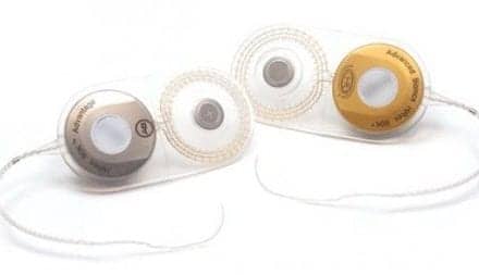
In response to this need, a 2-pole triple-throw toggle switch for BTE applications has been developed by Deltek using a sealed switch element (Figure 1). Focusing on an existing widely used BTE toggle switch, the company’s research and design team, working closely with hearing instrument manufacturers, evaluated different design solutions to prevent the exposure of the switch’s critical components to moisture and/or contamination. Laboratory research demonstrated that sealing the switch element provided the greatest protection.
The Model 2700 incorporates a completely sealed switch element made up of several “layers’ including a conductive layer and spacing layers completely sealed between polyimide layers. To incorporate this sealed switch, a pre-molded lead frame was developed that is precision-soldered to the switch element. It is dimensionally identical to existing older technology and therefore an easy replacement, In addition the new switch provides for customer design flexibility in mounting, because the leads can be formed into a horizontal position or remain straight.
To prove the benefits of this new design, Deltek retained the services of an independent testing laboratory to subject the new switch and a switch currently in use to accelerated environmental tests as a means of simulating long-term impact of perspiration and contaminants on switch failure.
Test Methods
A representative sample of 40 Deltek 2700 switches (test switches) and 43 switches with standard technology (competitive switches) were subjected to accelerated environmental testing by Trace Laboratories, an independent testing laboratory located in Palatine, Illinois.7 Prior to environmental testing, all of the test units were subjected to 8,000 cycles to represent normal operational wear and tear of the unit in the field. The switches were then exposed to salt fog testing in a salt fog chamber in accordance with EIA-364-26B and ASTM-B-117-97 test standards. Salt fog is often used to replicate hearing aid exposure to real world perspiration, as well as exposure to salt water contamination (eg, during boating, at a beach, etc).
The samples were tested so that uniform exposure was ensured for all switches. The chamber was filled with a fog that was made up of a solution of 5% by weight salt and 95% of weight distilled or deionized water. The temperature and humidity of the test tank was maintained at constant levels according to the designated specification. The samples were exposed to the continuous fog of saltwater solution (per ASTM B-117-97 test) for a total duration of 48 hours. After the 48-hour exposure, the samples were removed from the chamber and allowed to dry at laboratory ambient conditions.
Prior to the fog chamber test, resistance was measured across the end terminals, as close to the insulator body of each switch as possible using a Hewlett-Packard digital multimeter. The samples were wired in such as manner that a test voltage of 1.5 V (direct current) could be applied with a test current of up to 250 milliamps (mA, direct current) flowing through each sample. Upon completion of the salt fog test, the resistance of each switch was again measured. All pre and post measurements were recorded in milliohms (m
After evaluating the post resistance score, each switch was classified as within specification, out of specification, or as a catastrophic failure (eg, the switch was at infinite resistance and, for all practical purposes, was completely inoperable, meaning the hearing aid would not function properly, if at all). Since some switches exhibited catastrophic failure as a result of the salt fog test, we determined that an assignment of a 500 m
.gif) Figure 2. Impact of salt fog on competitive and test switch.
Figure 2. Impact of salt fog on competitive and test switch.
Results
Figure 2 shows post salt fog results for the competitive and the test (Deltek) switches. Of the competitive switches, 51% were within specification compared to 90% for test switches. Close to 26% of competitive switches exhibited catastrophic failure due to complete corrosion and breaking of contact leads, while an additional 23% of competitive switches had contact resistance in excess of the stated maximum specification at the completion of the testing (Figure 3). In comparison, none of the test switches exhibited failure due to lead breaks from corrosion, and only 10% of the test switches exceeded the maximum contact resistance threshold. Using the outcome classification scheme discussed earlier, the differences between the test and competitive switches were shown to be statistically significant (Chi-square = 16.86, df=2, p<.0002). The probability is 2 in 10,000 that the differences are due to chance.
.gif) Figure 4. Change (in mž) due to salt fog test.
Figure 4. Change (in mž) due to salt fog test.
A second method for evaluating the switches in adverse environments is to evaluate changes in resistance due to the salt fog test (Figure 4). Competitive switches exhibited an average change of 172.5 m
Conclusions
This laboratory experiment demonstrates that sealed switch technology results in increased resistance to failure from moisture or contaminant intrusion than standard toggle switch technology. In this laboratory test, the use of sealed switch technology was shown to improve switch reliability by 40%. These results corroborate a three-year investigation by a European-based hearing aid manufacturer who determined that the sealed switch technology reduced returns due to switch failure by one-third.
| This article was submitted to HR by Bryan Knott, senior product manager at Deltek, a div of Knowles Electronics, Elgin, Ill, and Sergei Kochkin, PhD, director of market development and market research at Knowles Electronics, Itasca, Ill. Correspondence can be addressed to HR or Bryan Knott, Deltek, 440 South McLean Blvd., Elgin, Illinois 60123; email: [email protected]. |
References
1. Kochkin S. MarkeTrak VI: Consumers rate improvements sought in hearing instruments. Hearing Review. 2002;9(11):18-22.
2. Kochkin S. MarkeTrak IV: Correlates of hearing aid purchase intent. Hear Jour.1998;51(1):30-41.
3. Kochkin S. MarkeTrak III: Why 20 million in US don’t use hearing aids for their hearing loss. Hear Jour. 1993;46(1):20-27;46(2):26-31;46(4):36-37.
4. LoPresti J, Kochkin S. Improving hearing instrument reliability with ferrofluid damped receivers. Hearing Review. 2003;10(1):44, 46, 51.
5. Kochkin S. Finally a solution to the wax problem. Hearing Review. 2002;9(4):46-48.
6. Kochkin, S. The effectiveness of a wax protection system in reducing receiver replacements. Hearing Review. 2001;8(9):40-41.
7. Trace Laboratories. Switch resistance and salt fog test report (S.O. No. 22109-03). Palatine, Ill: Trace Laboratories; May 27, 2003.