A New High Fidelity Digital Hearing Instrument Processor
A technical report on Gennum Corp’s new Paragon system, as well as a discussion of the importance of dynamic range, bandwidth and signal integrity for digital instruments.
Read More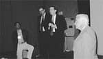
A technical report on Gennum Corp’s new Paragon system, as well as a discussion of the importance of dynamic range, bandwidth and signal integrity for digital instruments.
Read More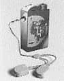
In response to a previous HR article on why trial periods may be detrimental to the acceptance of hearing instruments, the author presents a counterpoint on why trial periods remain a necessity for the hearing care field.
Read More
The AuD poses rewards for both students and their professors, and it is transforming university courses by infusing into programs the experiences of practicing audiologists.
Read More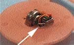
Starting a new AR program can seem overwhelming when schedules are full and professional demands for time are many. This article can serve as a resource for busy hearing care professionals who have considered expanding the rehabilitative aspect of their practice for adult patients but don’t know where to start.
Read MoreOwning the building in which your hearing care office or practice is located has several substantial financial rewards. This article provides hypothetical renting-versus-owning comparisons and points out several of the long-term merits of owning your own office building.
Read More