Audiology Summer Camp Offers Practical Knowledge for Graduates
The annual Oticon Summer Camp provides an intensive course in “real life audiology.”
Read More
The annual Oticon Summer Camp provides an intensive course in “real life audiology.”
Read More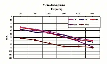
A technical review of the GN ReSound Canta7 series and its beta clinical trial results.
Read More
A look at feedback from an engineering control perspective, and explanations and commentary on the evolution of past and present DSP noise cancellation strategies.
Read MoreIs your practice doing everything to capture profits from its battery sales? If not, here are some reasons why it should, as well as practical tips for enhancing the marketing of both batteries and your practice.
Read More
The Better Hearing Institute has initiated a CD-ROM-based program designed to assist dispensing professionals in obtaining new referrals from primary care physicians. The educational program includes CME accreditation for doctors and staff—a first of its kind for any field.
Read More
Boys Town National Research Hospital recently celebrated its 25th anniversary of being a leading research center in pediatric hearing care science. HR looks at current research being conducted at the facility, which includes work on OAEs and ABRs, pediatric amplification, psychoacoustics and neurobiology, and genetic research into syndromic and non-syndromic hearing loss.
Read More