By Marshall Chasin, AuD
Have you forgotten all of the neat acoustics that were clinically necessary for working with hearing aids back in the 1980s? Some of what we, as a field, may have forgotten is increasingly resurfacing in the form of basic problems related to open and occluded fittings. For example, can you explain the various elements of the real-ear coupler difference transfer functions when it comes to deep-canal hearing aid fittings? What about the benefits of flaring out a slim tube in a non-occluding behind-the-ear (BTE) style hearing aid? Is an acoustic solution any different than merely turning up the high frequency gain electrically? And why don’t we use acoustic resistance anymore while fitting modern slim-tube hearing aids? Is there a reason, or is it simply more efficient to equalize out an unwanted resonant peak by using the hearing aid fitting software?
Initially, this article was called “Forgotten Acoustics” because it focuses on the acoustical laws of physics that every clinician needed to know in the 1980s and earlier. Since the advent of digital hearing aids in the 1990s, much of this knowledge has been relegated as “redundant.” Some may find this article to be a glimpse into how the last generation of audiologists may have functioned, and some, like myself, may just find the explanations about why things are the way they are to be interesting.
The laws of acoustics in this article are the same laws that can be applied to speech acoustics to better understand the vocal mechanism in human speech. And these are the same laws that help us decide how to design and set up a home stereo system or to better understand the acoustics of many musical instruments.
The order of this article is covered under the following headings, and the findings are as equally applicable to speech acoustics or how a musical instrument functions:
- Standing waves;
- Impedance and damping; and
- Amplification and flaring of a tube.
Standing Waves—They Are Everywhere… Well, Almost!
Whenever there are reflections of a wave, you can get sound energy flowing in two (or more) different directions: the incident wave and the reflected wave. As they pass in the night (or in a tube), they add up constructively and also destructively.
There are points in a room where a reflected wave may cancel the incident wave, and if you are unlucky enough to be in such a location, sound is reduced. These nulls or nodes occur in performance venue halls at musical theatres—the more of them there are, the poorer is considered the hall. Imagine a violinist tilting their head slightly and receiving a different sound than if sitting upright. This can happen. Welcome to the field of architectural acoustics!
These same standing waves, brought about by an interplay between constructive interference and destructive interference, also can occur in tubes. In fact, the only place they don’t occur is in a free field, such as when skydiving or when seated in an anechoic chamber. And, like standing waves, there are tubes everywhere: in our vocal tract when uttering vowels and nasal sounds, in musical instruments like the trumpet, and even in BTE hearing aids. There are no standing waves in custom hearing aids simply because the tubing length is so short (actually there are, but the first resonant peak associated with standing waves in a canal or CIC hearing aid occurs above 8000 Hz or above the range that frequencies are typically amplified).
So now you know the answer to the question, “What do skydiving and CIC hearing aids have in common?” No standing waves.
The quarter-wavelength resonator. The most important tube in the hearing field is one that is open at one end and closed at the other end—a tube called a quarter wavelength resonator. BTE hearing aids are “closed” at the receiver end and “open” at the tip of the earmold tubing. This is also true of our vocal tracts, which are “closed” at the vocal chords and “open” at the lips during the articulation of [a] as in “father.” And it is also true of a trumpet: “closed” at the lips and “open” at the end of the bell.
Quarter wavelength resonators have odd-numbered multiples of the first mode of resonance. This may not sound exciting until one realizes that this explains the resonant pattern of the vowel [a] as in “father,” the spectrum of a trumpet, and the frequency response of BTE hearing aids. In the case of a BTE, the “tubing” length from the receiver, through the ear hook, and through the hearing aid tubing is about 75 mm long for an adult.
Using the equation shown in Equation 1 below (F=v/4L), assuming the speed of sound (v) at 340,000 mm/sec, and setting L = 75 mm, F equals 1000 Hz. That is, the first mode of resonance is at 1000 Hz, and then there are odd-numbered multiples of 1000 Hz, namely 3000 Hz, 5000 Hz, and 7000 Hz.
_____________________
Equation 1:
F = v/4L where…
F is Frequency (Hz)
v is speed of sound (34,000 cm/sec or
340,000 mm/sec)
L is the length of the tube (in cm or mm)
_____________________
Turning our attention to custom hearing aids, such as a CIC, let us assume that the tubing length is now only 10 mm from the receiver to the end of the shell. Again, using the quarter wavelength resonator formula with L = 10 mm, we find that F = 8500 Hz. Since this is typically above the frequency range of most modern hearing aids, we can safely say that there are no standing wavelength resonances for custom hearing aids; any resonances found in the frequency response of a CIC (or any other custom hearing aid) is due to the mechanical attributes of the receiver, and not the acoustical pathway.
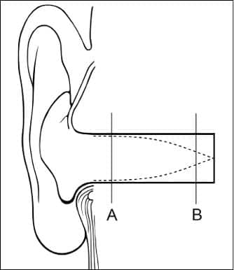
Another occurrence of a quarter wavelength resonator is in our ear canals, which are “closed” at the ear drum and “open” at the lateral portion of the meatal opening. Figure 1 shows the unobstructed ear canal with the first mode of a standing wave, which is associated with the 2700 Hz real-ear unaided response (REUR). Obstruction of the outer portion of the ear canal (grey area in Figure 2) with either wax or a pathological collapse of the cartilage (eg, polychondritis) will serve to significantly reduce the level of the associated resonance at 2700 Hz.
|
| Figure 1. An unobstructed ear canal showing a standing wave that corresponds with a 2700 Hz resonance. There is a large volume velocity at position A and a minimal one at position B. (See also text for Figure 2.) |

|
| Figure 2. Obstruction of the outer portion of the ear canal (at position A) with either wax or a pathological collapse of the cartilage (eg, polychondritis) will serve to significantly reduce the level of the associated resonance at 2700 Hz. If the obstruction was at position B, there would be minimal effect. |
In contrast, if the obstruction is near the tympanic membrane where there isn’t a lot of particle movement in the standing wave pattern (ie, near a node at position B), there would not be a significant change in the amplitude of the ear canal resonance. This is why ear canal occlusion with earwax may result in a significant high frequency conductive hearing loss (with its greatest effect around 2700 Hz).
This last example demonstrates another property of a wavelength-associated resonance; depending on where the obstruction is, there will be different effects on the amplitude of the resonant peak. This is a well-known phenomenon when acoustic dampers are used in hearing aid tubing to smooth the frequency response. If the damper is at a maximum of a standing wave (position A), there will be a greater destruction of the resonance than if the damper is at a nodal position (B) in the standing wave.
Returning to Figure 1, let us assume that the average adult ear canal length is 28 mm. Using the quarter wavelength formula from Equation 1, then…
F = 340,000 mm/sec/4 x 28 mm = 3035 Hz
Effective length. Why does this formula suggest that the resonance should be at 3035 Hz, but as measured using real-ear measurement techniques, the resonance is typically around 2700 Hz? This brings us to a discussion of length versus “effective length.”
It turns out that the measured length of a tube is only a first approximation of how sound is transmitted through the air. There are two additional factors that affect the real or effective length: the nature of the “closed” end and the nature of the “open” end. In the case of the human ear canal, the “closed” end is the tympanic membrane and this adds the equivalent of a few mm of acoustic length because of its compliance.
This is not surprising; if one were to measure the length of the Zwislocki coupler used in KEMAR, the measured length is 21.5 mm, yet it functions acoustically as if it was much longer. The REUR as measured in KEMAR is 2700 Hz, and the explanation is that the microphone that replaces the tympanic membrane in KEMAR adds most of the missing acoustic length—the diaphragm of the microphone is quite compliant, which adds 7-8 mm of “length.”
Turning our attention to the lateral end of the ear canal, this opening contains a mass of air called an inertance. The inertance oscillates as one unit and provides an additional several millimeters of acoustic length. It also can generate its own lower frequency resonance, and this is what occurs in earmold vents (also known as a vent-associated resonance).
So the frequency of quarter wavelength resonances, such as the “tubing resonance” in BTE hearing aids, or the real-ear unaided response (REUR), is governed by the formula in Equation 1. These resonances generate odd-numbered multiples of its mode or lowest frequency, and are altered by the physics of both the “open” end and the “closed” end. Of importance is that we have not discussed any effect on the amplitude of the associated resonances.
Impedance and Damping
The amplitude of the associated resonances found in a BTE hearing aid or musical instrument is well defined by simple acoustic principles. Equation 2 reflects the physics behind our acoustic immittance testing used routinely in a clinical setting. The equation shows that impedance (Z) is a function of both reactance and resistance. An interesting acoustic result is that, at resonance, reactance is 0. Using this fact, one can say that, at a resonant peak, the impedance Z is pure resistance.
Unlike reactance—which is frequency dependent—resistance is independent of frequency. The implication is that the amplitudes of the lower frequency resonances and the higher frequency resonances are similar and are more governed by the general properties of the tube; a trumpet has less resistance (damping) than the human vocal tract, but the higher frequency resonances in both cases are of similar amplitude as the respective lower frequency amplitudes.
_____________________
Equation 2:
Z=?reactance2+resistance2
at resonance, reactance = 0
_____________________
The hearing aid industry has used acoustic resistors (aka “dampers”) that can reduce the amplitude of the frequency response at resonant frequencies. However, depending on where the acoustic resistor is placed—at a node of a standing wave or at an anti-node of a standing wave—there are differing effects on the frequency response.
In the case of wax occlusion of the ear canal, since the wax is in the outer (lateral) portion of the ear canal where there is an anti-node (see position A in Figures 1 and 2), there is a great resistive affect. An obstruction in a more medial location (nearer a node such as position B) results in very little alteration of the amplitude of the resonant peak.
Specific impedance. This brings us to the wonderful world of specific impedance. Equation 3 shows the specific impedance of a tube, as well as an example of how to determine the specific impedance for #13 hearing aid tubing.
_____________________
Equation 3:
Z = ?v/area (cgs) where…
Z is the specific impedance
p is the density of air
v is the speed of sound
area is the cross-sectional area of tube (cgs)
For example, for #13 tubing:
Z = 0.0112 gr/cm3 x 34,000 cm/sec/0.314 cm2
Z=1212 ?
_____________________
If we use the cross-sectional area of standard #13 tubing commonly found with many BTE hearing aids, the specific impedance works out to be just over 1200 ? (ohms). This means that #13 hearing aid tubing requires about 1200 ? of resistance to fully reduce the amplitude of the resonances. The industry has used 1500 ? of resistance in the past, but this is close enough.
Thinner-diameter tubes, such as those found with slim-tube BTE fittings, require a significantly higher specific impedance to rid the frequency response of annoying resonances. And, for the human vocal tract with a relatively large cross-sectional area, very little acoustic resistance is required to alter the resonant pattern.
Amplification and Flaring of a Tube
The acoustic transformer effect is a fancy way of saying that, depending on the length of a tube, increasing its cross-sectional area enhances the amplitude of the higher frequency components. An even fancier way of saying this is that “the amplitude of all frequencies whose one-half the total length of the tubing are enhanced by having a flare or horn.” Now that’s a great line sure to impress your friends.
Equation 4 looks like the equation in Equation 1, as it is made up of the speed of sound (v) and the length of a tube (L), but that is where the similarity stops.
_____________________
Equation 4:
F = v/2L
_____________________
F is the frequency at which a flare would begin to enhance the amplitude of the sound. For a tube that is 75 mm in length, such as that of a BTE hearing aid for an adult, Equation 4 suggests that all frequencies above 2266 Hz (F = 340,000 mm/sec/(2 x 75 mm)) would be enhanced by having a flared tubing. For young children (with a total length of only 60 mm), the high frequency enhancement begins at 2833 Hz. That is, the shorter the tube, the higher frequency and the less the effect of a flare would begin at.
Libby horns are one example of tubing that gradually flares, but this also explains why opening one’s mouth wider during the articulation of some sounds generates an increased relative high frequency output. It also explains why trumpets and many other musical instruments use a flared tube.
Flared tubes as amplifiers. Finally, our trip through the land of the acoustics of tubes finishes with the amplification factor. Equation 5 shows an example of a doubling of the inner diameter of the tubing.
_____________________
Equation 5:
Amplification factor =
10log (?r2 of wider portion/?r2 of narrower portion)
For a doubling of inner diameter:
10log (22) = 2 x 10log (2) = 6 dB
_____________________
If the internal diameter doubles, such as with the 4 mm Libby horn where the inner diameter increases from 2 mm to 4 mm, then the maximum increase in amplitude above the frequency, shown in Equation 5, is 6 dB. Of significance, however, is that this is true for all doublings of inner diameters; it doesn’t matter whether the doubling is from 2 mm to 4 mm or from 1 mm to 2 mm. A thin tube that flares to the size of #13 tubing also will generate the same 6 dB of high frequency output.
One may ask whether this is equivalent to increasing the electrical output in a hearing aid by 6 dB. Although the end result would indeed be similar, there are two differences. With an acoustical flare of the tubing, the extra output is after the hearing aid receiver, so this would not deleteriously affect battery life. Additionally, the difference between the gain and the output in the high frequency region is not altered. Acoustical high frequency modifications maintain the necessary headroom.
Summary
There are many laws of acoustics that have been forgotten since the advent of digital hearing aids. While it is true that most of the modifications can be accomplished digitally now instead of acoustically, there are some subtle differences. The five basic equations provided here remind us why many things are the way they are today in the realm of hearing aids.

|
Marshall Chasin, AuD, is the director of auditory research at the Musicians’ Clinics of Canada in Toronto and the coordinator of research at the Canadian Hearing Society. He is also an associate professor in the School of Communication Sciences & Disorders at the University of Western Ontario, and adjunct professor at the University of Toronto (in Linguistics) specializing in Acoustic Phonetics. CORRESPONDENCE can be addressed to Dr Chasin at: [email protected]. |