The recent introduction of digital hearing aids with adaptive signal processing algorithms, such as an adaptive directional microphone system, can make trouble-shooting more challenging. Dispensing professionals may misinterpret the potential artifacts of an adaptive algorithm as a symptom of a defective component, prompting a return of the hearing aid to the manufacturer for repair when in fact no “true” component defect exists.
An accurate interpretation by the dispensing professional is required for problem identification. However, existing test methods may not be able to isolate a component/functional problem in a hearing aid. In addition to obscuring the true cause of a patient complaint, sending a hearing instrument back for repair/replacement when there is no component defect unnecessarily deprives the patient of the use of the aid.
A simple tool that can quickly identify component defects may facilitate the trouble-shooting process and assist in establishing the origin of a patient’s complaint. Once a component defect is ruled out, the dispensing professional can focus on adjusting the appropriate programming parameters relevant to the complaint, and/or educate the patient on the potential artifacts associated with the particular adaptive algorithm.
This article describes the mechanism of a screening test (the Self-Test™) made available by Widex for the Diva hearing aid, as well as the results of a preliminary study that support the system’s efficacy.
Assessing Components
The benefits of utilizing digital signal processing in hearing aids include increased flexibility and effective processing at a reasonable current drain.1 Another benefit is the potential for hearing aids to generate their own signals. These signals may be used for various purposes such as in-situ threshold measurements during hearing aid fittings2 and estimating the maximum permissible gain and feedback path with the hearing aids in-situ.3 The Self-Test further expands the use of self-generated signals.
The Self-Test has been developed to assist the dispensing professional in determining if a problem reported by the hearing aid user is component-related. The underlying principle of the test is that the magnitude of a calibrated signal—measured at different stages of a hearing aid circuit—may be used to reveal the integrity of a particular component and those preceding it.
During the test, the Diva hearing aid first generates signals of known frequencies and intensities. The magnitude of these signals is then measured at different stages and compared to their references throughout the hearing aid circuit in order to evaluate the integrity of individual components (ie, amplifiers and transducers) in the instrument. The diagnostic procedure is accessed via the same fitting software (or programmer) used to program the instrument.
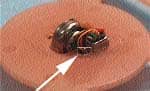
To perform the test, the hearing aid is connected with the same cable used for programming, placed in the Widex Self-Test cylinder (Figure 1), and tested via a portable programming device or the PC-based fitting software. The test cylinder provides a feedback path from the output of the hearing aid to its input to ensure sufficient coupling. Although a sound booth is not necessary to conduct this test, the test should be performed in a quiet room where the level of the environmental noise is kept to a minimum.
Figure 2. Flow chart of the self-test. If the test detects a problem at any of the parameters in the left-hand column, it generates a prompt (right-hand column).
Figure 2 shows the sequence of operations of the test. There are two main stages of operation. Stage 1 evaluates the integrity of the digital signal processor and ensures that the appropriate environmental test conditions meet the required criteria. Once the test is activated with the selection of [Start Test], communication between the instrument and its programming device is evaluated. If a problem is identified, an “Error” message is displayed, indicating that the instrument cannot be programmed and should be returned to the manufacturer for repair. Following the communication test, a series of internal tests are performed to assess the integrity of the signal processor, such as a measurement to ensure that the instrument is able to “read” and “write” programmed data. A problem at this stage would result in an [amplifier] error. The absence of an amplifier error assures the dispenser that special processing in the instrument, such as noise reduction, works according to its design specification. The environmental noise is then measured to determine if the room is quiet enough to perform further testing. If the ambient noise level exceeds approximately 55 dBA, a [Room Noise] message is displayed and testing is terminated.
Stage 2 of the test evaluates the integrity of the transducers used in the hearing aid. Modulated sinusoids of known frequencies and intensities are generated within the hearing aid and presented via the hearing aid receiver. The signals re-enter the hearing aid through the microphone inlet(s). They are tracked at various stages of the instrument in order to assess how the input is processed. An abnormality in the output characteristics of the A/D converter will result in an [Amplifier] error. In the absence of a problem at this level, the magnitude of the signal will be analyzed at the level of the receiver and microphone(s). A [Sound Outlet] error will result if the receiver opening is clogged with debris or if a receiver failure occurred (eg, receiver damaged after hearing aid dropped on floor). If a microphone is weak or if a microphone port is clogged, a [Check Microphone] error will be displayed. Because a weak signal could indicate problems at the microphone and/or the receiver, a proprietary algorithm is used to differentiate the origin of the problem. In the case of a dual-microphone system (eg, Diva ITC instrument), the suspected faulty microphone will be identified (eg, a [Check Rear Mic] prompt will be displayed). Finally, the instrument’s telecoil is evaluated. A malfunction will result in a [Telecoil] error.
If the result of the analysis through each component stage meets the required criteria, the result of the self-diagnosis is [OK] and there should not be any component defect within the instrument. In other words, an [OK] result indicates that the instrument is functioning in its intended manner. In this case, the complaint of the wearer may be a result of parametric settings or artifacts of special processing. The entire procedure—including connection of the instrument to the programming adapter, accessing the software, and obtaining results—is completed in less than 2 minutes.
Clearly, efficiency cannot be the only criterion to measure the usefulness of a screening tool. How accurately the test identifies a true component problem when there is indeed a problem with the component (correct identification rate) is important in establishing the sensitivity of the test. Likewise, how accurately the test results indicate no component problems when indeed there are none (correct rejection rate) is also important to the sensitivity of the test. These two values represent the efficacy of the screening test.
A sensitive procedure will generally have a combined rate of over 80%. As with any clinical procedure, especially those intended as screening devices, a small percentage of “misidentifications” would be likely. A misidentification occurs when the results of the test suggest a component problem when in fact there is no component problem (false positive), or when the test results suggest no component problems when in fact there is a component problem (false negative). Clearly, a good screening tool should have a low incidence of false positives and false negatives in order to be useful. The purpose of the present study was to determine the sensitivity of this screening test in evaluating the integrity of functional components in the hearing aid.
Study Method
This study examined data collected for 200 custom Diva hearing instruments (100 ITE/ITC, 100 CIC) sent to the manufacturer for repair of various suspected component defects. Dispenser reports such as “dead,” “weak”/“fades,” “static”/“noisy,” and “distorted” are indicative of component defects. Of these 200 hearing instruments, 60% were reported “dead.” Twenty percent (20%) were reported “weak” or “fades.” Ten percent (10%) were reported as “static” or “noisy,” and 10% were reported as “distorted.” These statistics reflect the typical distribution of dispenser repair reports received by this manufacturer for the various product lines.
The Self-Test was performed in a quiet, 10 ft by 11 ft carpeted room. Results were entered into a database by the study audiologist. Instruments were then sent as routine repairs through the service department. Repair technicians were blind to the results of the Self-Test. Diagnosis and repair activities for the instruments were retrieved retrospectively for this study.
Assessment by Service Lab Technicians
All hearing aids evaluated by the service department undergo a comprehensive and time-intensive diagnostic evaluation by technicians who have an average of four years repair experience. Furthermore, technicians have many tools available to them (eg, microscope, specialized diagnostic software programs, hearing aid analyzers, volt-ohm meters, and transducer analyzers) to evaluate the integrity of hearing aids. For this reason, the results of service lab assessment are used as the benchmark for determining the functional status of the components in the hearing aids. These results will be compared to the results of the Self-Test. A description of typical service lab procedures follows.
Figure 3. Flow chart of service lab diagnosis.
A flow-chart of the diagnostic procedure followed by the technicians is shown in Figure 3. Stage I of service lab diagnosis includes interpretation and verification of the dispenser’s report and a visual inspection of the integrity of all wiring connections, contacts, tubing, and suspension for the receivers and microphones. It is important to note that neither the Self-Test screening tool nor the hearing aid analyzer can replace a visual inspection by an experienced technician.
Stage II of service lab assessment includes testing of communication between the hearing aid and the programming software, and testing of the integrity of individual components. This segment of the evaluation process corresponds to the initial steps in the automated sequence of the Self-Test procedure. The hearing instrument is connected to a personal computer, then utilizing diagnostic software, the communication between the instrument and the programming device is assessed. The integrity of the battery contacts and the level of the current drain are evaluated using a volt-ohm meter. These tasks are not performed in the Self-Test since the adapter used by the dispenser for programming custom products (through which the test is accessed) requires a different power source and contact points than those used with a conventional battery. The Self-Test procedure therefore has limited ability to recognize intermittent problems resulting from poor battery contacts or those resulting from use of poor quality batteries.
The technicians use proprietary diagnostic software to test each individual component in order to isolate the origin of the problem. The integrity of the instrument’s receiver and microphone (or each microphone in the case of the dual microphone instruments) is assessed by examining their frequency response characteristics, comparing the levels of known voltage at different stages throughout the circuit, and measuring the responses of the individual transducer when necessary. Templates of acceptability are readily accessible to the technicians for comparison. The functions of the A/D converter, input amplifier, and AGC are assessed in a similar manner. For instruments with a telecoil, the telecoil response is evaluated for various input signals and the frequency responses of the telecoil are obtained. The Self-Test is able to identify microphone, amplifier, and receiver abnormalities; however, its use is limited in the identification of components that exhibit distortions because distortion measurements require a very quiet environment. Accurate distortion analysis can only be performed in a sealed sound chamber and not in an open cylinder where ambient noise can easily contaminate the measurement.
If the technician’s analysis is positive for a component defect, more extensive analysis and troubleshooting are performed. The circuit is removed from the shell and the voltage is measured at different stages of the instrument circuit. The defective component is replaced, and measurements are repeated for the entire circuit. For example, if a problem is identified at the microphone, it is replaced and measurements are repeated throughout the circuit. If the results continue to be abnormal, the possibility of a receiver problem is explored. This process is repeated until the measured value at each component stage, as well as that of the entire circuit, is within an acceptable range.
A screening tool such as the Self-Test does not have the advantage of the information obtained through such systematic time-intensive measurements. It is also limited in its ability to isolate the origin of problems if multiple problems are involved.
Results
The efficacy of the Self-Test in correctly identifying component problems can be presented in a 2 x 2 matrix (Table 1). There are two dimensions to this table. The left hand-side of the table, labeled “Functional Status,” represents the true functional status of the hearing aids as determined by the technicians. Here results of technician evaluation are categorized as “No Problem” (no component problem identified by technician) or “Problem” (technician found a problem). Results of the second dimension, “Self-Test Outcome”, either indicate “Problem” (any result other than [ok] (eg, [Check Rear Mic]) or “No Problem” ([OK] result). Entries within each cell represent the total number of hearing aids that meet the criteria as defined by both dimensions. These cells are labeled A-D.
An objective of the test is to accurately identify hearing aids with component problems. Cell “A” displays the number of hearing aids that have component problems as determined by the technician (a functional status problem) and also are identified by the self-test as having component problems. Thus, this cell represents the correct identification rate. In this case, a total of 141 (70.5%) hearing aids (69 ITEs and 72 CICs) are in this category.
Cell “B” represents the number of hearing aids that have component problems but are identified by the test as functioning properly (ie, false negative rate). Obviously, the false negative rate should be as low as possible so that functioning components are not identified as defective. Of the total 200 hearing aids sent in for repair, 25 (12.5%) hearing aids (10 ITEs and 15 CICs) are in this category.
Cell “C” represents the number of hearing aids identified by technicians as having no component problems but are identified by the test as having a component problem (ie, false positives). Ideally, the false positive rate should also be as low as possible. In this case, no hearing aids (0%) belong to this category.
Cell “D” represents the number of hearing aids that are identified as having no component problem by both the test and the technician (ie, the correct rejection rate). There are 34 (17%) hearing aids in this category (13 ITEs and 21 CICs).
Ideally, the number of hearing aids reported in cells “A” and “D” together should be as high as possible so the overall hit-rate of the procedure (ie, (A + D) ÷ (A + B + C + D)) is high. In this case, the overall hit-rate is 87.5%. On the other hand, the number of hearing aids reported in cells “B” and “C” combined should be small so the overall miss rate of the procedure (ie, (B + C) ÷ (A + B + C + D)) should be low. In this case, the overall miss rate is 12.5%.
Discussion
The results of the present study show that the Self-Test has a high overall hit-rate (87.5%) and a low overall miss rate (12.5%). This suggests that one can trust the results of the test with high certainty.
There are several observations that are important to note. Of the 141 instruments which the Self-Test identified with a component problem, all (100%) had true component defects as identified by the technicians. This suggests that a consistently abnormal test result indicates a high likelihood for some type of component defect. When such results are obtained, the dispensing professional should attempt to address the problem (eg, clear the microphone port of debris if the messge displayed is [Check Mic]), then repeat the test. If the error message continues to appear, the professional should send the instrument to the manufacturer for further evaluation.
Of the 200 hearing instruments examined, 25 (12.5%) of them were identified by the test as functioning properly [OK] but were identified as having a component defect by the technicians. This reveals that the test would miss some hearing aids that are identified as defective by the technicians. An examination of these missed hearing aids reveals that, in at least some cases, the test would not have been expected to identify the cause of the problem. Situations which can increase the number of false negatives include intermittent problems, battery contact problems, and internal feedback.
Therefore, there are some caveats to consider when using the test. The procedure will only identify an intermittent problem if that problem manifests itself during the test. Because the test is performed with the custom instrument connected to a programming adapter and not to a battery, battery contact problems may not be identified. It should also be noted that variability in environmental room noise (eg, telephone ring, spurious sounds, and instrument positioning that results in a receiver opening or microphone leaning against the wall of the cylinder) could influence the outcome of this procedure. Additionally, the test does not have the advantage of visual inspection available to the technicians. Nonetheless, these findings suggest that when the test is performed in the context of a patient complaint and if an [OK] result is obtained, the dispensing professional should repeat the test and use other measures (eg, electroacoustic tests, visual inspection, consulting with the manufacturer) to supplement the diagnosis.
The preponderance of problems identified by the Self-Test procedure in this study were sound outlet (receiver and receiver port) problems, followed by microphone problems. Typically, the complaint is “weak/fades” or “noisy/static” if the problem is microphone-related. Complaints such as “dead” or “silent” are usually receiver-related. Complaints such as “distorted” are either microphone or receiver-related. This is consistent with typical repair lab statistics for custom instruments. Additionally, the incidence of amplifier and telecoil defects was extremely low (less than 1%), consistent with the reliable functioning of these components.
A significant percentage of instruments are received for manufacturer assessments that are negative for component problems. In this study, 34 of the hearing aids (17%) were identified by both the Self-Test and the technicians to be negative for a component defect. These are accompanied by various dispenser reports and generally are the result of gain mis-adjustment or are program-related. In the future, use of the Self-Test procedure may decrease the number of instruments sent to the manufacturer unnecessarily and direct the dispenser to initiate program adjustments when appropriate. Time can be saved if the dispenser performs this test prior to making program adjustments or sending the instrument to the manufacturer for component assessment or remake. Results of this study indicate this procedure is a viable method for identifying component defects of hearing instruments and may be used with success to supplement more traditional troubleshooting.
Digital signal processing does not only improve the flexibility and fidelity of sound processing. Results of this study indicate it also expands the tools available to dispensing professionals for fine-tuning and trouble-shooting a patient’s hearing aid complaint.
Acknowledgement
The authors thank Stanley Yule, repair supervisor at Widex Hearing Aid Co., for his assistance in data collection.
| This article was submitted to HR by Jane Auriemmo, AuD, an audiologist at Widex Hearing Aid Co, Long Island, NY; Kim Nielsen, MS, product manager at Widex A/S, Vaerloese, Denmark; and Francis Kuk, PhD., director of audiology at Widex Hearing Aid Co, Lisle, Ill. Correspondence can be addressed to Jane Auriemmo, AuD, Widex Hearing Aid Co, 35-53 24th St, Long Island City, NY 11106-4116; email: [email protected]. |
References
1. Westermann S, Sandlin R. Digital signal processing: Benefits and expectations. Hearing Review. 1997;4(2):56-59.
2. Ludvigsen C, Topholm J. Fitting a wide range compression hearing instrument using real-ear threshold data: A new strategy. Hearing Review. 1997;2:37-39
3. Kuk F, Ludvigsen C, Kaulberg T. Understanding feedback and digital cancellation strategies. Hearing Review. 2002; 9(2):36-41, 48-49.