A new invention and process is proposed for providing the global market with an automated method for designing custom hearing aid shells and earmolds from digitized ear impressions.
By Chester Pirzanski
The shape of a custom shell for a hearing aid is derived from an impression taken from the patient’s ear. There are currently two methods of impression shaping into custom shells: 1) The older method of manual impression shaping, and 2) the newer method combining computer-aided modelling and 3D printing.1-6
In the older method, the impression is shaped manually by a technician with the use of mechanical cutters and grinders. The newer method employs computer-aided modeling software to virtually shape a digitized ear impression obtained by 3D scanning of a silicone impression. Both the manual and computer-aided shaping methods are time consuming, subjective, intuitive, and not free from inaccuracies. Inaccuracies in impression shaping result in shells that have a poor fit and are subsequently returned to the manufacturer with either a request for a new hearing aid, or a request for a refund.
What makes computer-aided shaping subjective and intuitive is that modeling a well-fitting shell involves more than duplicating the shape of the ear impression.1 To make a shell that is easy to insert into the ear, has a secure and comfortable fit, and is sealed adequately in the ear against acoustic feedback, the ear impression must be modified in several ways: the canal is cut to proper length and tapered; the shell is made with a snug fit at the canal aperture; and the concha is shaped to accommodate the electronics and fit inconspicuously in the ear. This is where the modeler’s experience is critical.
Since there are no industry-wide standards for impression modeling, each manufacturer has their own guidelines, and each modeler makes individual decisions within those guidelines while shaping impressions. Even with extensive training, variances exist in final shell designs produced by any individual modeler—thus, so do differences in the resulting shell fit.
I estimate that over 2 million custom hearing aids and 6 million custom earmolds are made annually. This translates into the employment about 400 modelers and more than 100,000 modeling hours, amounting to an annual cost of $10,000,000 solely from human resources. Additional expenses include, but are not limited to, computers capable of running real-time 3D rendering and editing software, as well as the licensing costs for the modeling software, costing upwards of $2,000,000. With all these labor-related expenses, automated shell modeling appears a more cost-effective approach to manufacturing custom hearing aids.
The first attempts to automate shell modeling emerged in early 2000’s. In most cases, the invention disclosed a process where an ear impression is matched with a pre-modelled shell stored in a computer database. This method requires a large number of pre-modelled shells in order to cover a nearly unlimited number of human ear shapes and sizes, and the great variety of custom hearing aid styles and options. Due to the fact that the selected shell was originally modeled for another individual, it will have only a limited fitting accuracy in the patient’s ear, resulting in a potentially imperfect fit. In addition, the selected shell may be inadequate to accommodate the necessary components and options for the hearing aid required by the patient, thus rendering the selected shell useless for hearing aid assembly. For the above reasons, the concept of impression-shell matching appears unworkable.
A New Method for Shell Automated Modeling
This innovation for shell automated modeling was made feasible by recognizing two fundamental factors: 1) Human ear impressions share common contour lines, regardless of their size and shape. 2) Any seemingly unsolvable challenge can usually be solved by breaking it to smaller solvable problems.
In this invention, three patented solutions are used to model impressions into hearing aid shells by the modeling of: the canal module, the anterior concha module, and the posterior concha module. The shape of each module is derived from a given impression and is fully customized to match the shape of the ear. At the end of modeling, all three modules are integrated into a hearing aid shell.
This innovative method is suitable for modeling all shell styles, which include, but are not limited to, Full-shell and Half-shell In-the-Ear (FS/HS ITE), Canal (ITC), Completely-In-Canal (CIC), and Invisible-In-Canal (IIC). This method can also be used for modelling shell options such as Canal-lock and Helix-lock, and custom earmolds.
Key Features
The canal module. The author’s research found that the contour line of the canal aperture on most ear impressions can be duplicated with one of four 2D templates. Each of the four templates has a predetermined shape, and its curvature is anatomically accurate and designed to optimize the fit of the shell in the ear. The templates feature functional areas that include the acoustic seal area, retention area, insertion area, and
comfort area. These areas closely correspond with the ear anatomical features, such as the canal cartilage, the bony tissue, the canal first bend, and the canal widening past the first bend.
There are two types of templates: anterior-posterior (AP) plane templates, and superior-inferior (SI) plane templates. The virtual modeling begins with the insertion of an AP template into the canal to the depth required for the custom product, as illustrated in Figure 1a.

The template is alternately stretched across the canal and rotated to achieve the target fit accuracy at the canal aperture, see Figure 1b. If the target fit accuracy is not achieved, another template having a different curvature is fitted in the canal in the same fashion. This process of template changing and fitting continues until an AP template with a good fit is found.
Impression shaping in the superior-inferior plane with SI templates follows, as illustrated in Figure 1c. The number of the AP templates and SI templates employed depends on the targeted shell fitting accuracy. The selected AP and SI templates are assembled into a 3D virtual shell frame, which is surfaced and becomes the canal module for the shell.

The anterior concha module. This module is shaped with the use of a faceplate module that encompasses hearing aid components mounted on a faceplate. The components are covered with a dome. Each hearing aid style requires at least one pre-modelled faceplate module. The actual number of pre-modelled faceplate modules depends on the optional positions of movable electronics and the varying ear concha shapes.
The faceplate module having the highest fit rate for the requested hearing aid style and options is selected from a computer database and inserted into the digital impression. Through motion and rotation, the selected faceplate module is placed with a collision-free fit (Figure 2a). The position and orientation of the selected faceplate module in the digital impression are to meet specific fitting rules previously stored and associated with the hearing aid style. This includes, but is not limited to the battery door orientation, the faceplate module alignment in the concha, and the microphone module alignment with the horizontal plane. If a collision-free fit of the selected faceplate module in the digital impression cannot be achieved and/or the specific fitting rules are not met, another pre-modelled faceplate module is selected and fitted.
This process of the faceplate module selecting, fitting, and changing continues until a faceplate module with a satisfactory fit is found. The fit of the selected faceplate module in the digital impression is customized with a buffer, as shown in Figure 2b. The buffer does not trigger collisions with the impression. In areas, for example X and Y, where the buffer crosses the contour line of the impression, the buffer is modified to accommodate the shape of the ear. The selected faceplate module and the modified buffer are merged into the anterior concha module, see Figure 2c.

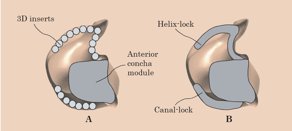
The posterior concha module. This module is required for full-shell hearing aids and options such as Canal-lock and Helix-lock. The areas of the helix, tragus, and anti-tragus feature undercuts overhanging hollow spaces. The posterior concha module resides in those hollow spaces and enhances retention for the shell. The posterior concha module is modeled with 3D inserts placed in the concha undercuts, as required for the shell style, as shown in Figure 3a. The fit of the 3D inserts is customized with a buffer in a fashion similar to customizing the fit of the faceplate module in the anterior concha. The customized 3D inserts are merged into a posterior concha module. Figure 3b shows posterior modules for Canal-lock and Helix-lock.

The hearing aid shell. The shell modeling process is concluded by integrating the canal module, the anterior concha module, and the posterior concha module into a 3D virtual custom hearing aid shell, as displayed in Figures 4a-b (a full-shell posterior module shown). The shell is fully customized and will fit only in the ear of the individual requesting the hearing aid. The shape and size of the shell are adequate to accommodate all electronics at proper locations.
Benefits of the Invention
This innovative virtual shell modeling method has the potential to benefit all involved in the hearing instrument industry: the patient, the clinician, and the manufacturer. The most obvious direct benefit is the automation of shell modeling that has the potential for significant time and cost savings. The second benefit is that the manufacturer can create their own templates that reflect their modelling philosophy.
These templates can be first tried locally, tuned for best performance, and then become the manufacturer’s global standard. This is designed to solve all local modeling differences and greatly reduce hearing aid returns due to a poor fit and protrusion from the ear. Hearing aid shells that cannot be modeled with the existing selection of the templates will be modeled by a team of experts, and the resulting new templates and modules will then be included in a computer database, so eventually all shells are automatically shaped.
A 24-hour hearing aid manufacturing turnaround time should become the standard for custom products using this system. It is conceivable that with all-electronic orders that include in-office impression scanning or direct ear scanning, the manufacturer will be able share with the clinician the image of the modeled shell almost instantly after receiving the order. In this way, the clinician will know that the shell meets their expectations regarding the hearing aid fit and cosmetic appearance. The patient will benefit from receiving a hearing aid that is done right the first time, with a secure and comfortable fit in the ear.
Acknowledgements
The developer of this automated virtual impression shaping method will sell or license the manufacturing rights to qualified organizations. These organizations should be capable of producing custom hearing aids and/or accessing the appropriate markets with the product. This automated impression shaping method is protected by US patents 10158954, 10325404, and 10325418 in the United States. Other territories are being considered on an as needed basis.
References
- Pirzanski C. The anatomy of a perfect ear impression. Hearing Review. 1998;5(12):2-24.
- Pirzanski C. Factors in earmold style selection: Starting (and finishing) right. Hearing Review.2001;8(4):20-24.
- Pirzanski C. Earmolds and hearing aid shells: A tutorial, Part 2: Impression taking techniques that result in fewer remakes. Hearing Review. 2006;13(5):39-46.
- Pirzanski C. Earmold retention issues: Why do these earmolds keep falling out? Hearing Review. 2010;17(5):26-34. Available at: www.hearingreview.com/issues/articles/2010-05_02.asp
- Pirzanski C, Berge B. Is the end near for acoustic feedback? Hearing Review. 2004;11(4):18-23. Available at: www.hearingreview.com/issues/articles/2004-04_01.asp
- Pirzanski C. Earmolds and hearing aid shells: A tutorial, Part 5: The manufacturing of conventional and digital earmolds. Hearing Review. 2006;13(10)[Sept]:22-28.

About the author: Chester Pirzanski is a retired engineer with 25 years of industry experience and expertise in researching, manufacturing, and training on various aspects of hearing aid fittings.
Correspondence can be addressed to: [email protected]


