Hearing Aid Fitting Tips | March 2018 Hearing Review
A useful trick for improving your patients’ experiences with RIC receiver insertion.
If you’re like a lot of hearing care professionals, it drives you crazy whenever you see a hearing aid wearer with an improperly inserted RIC receiver. Here is a simple and easy-to-do dispensing trick for facilitating a patient’s insertion of a RIC non-custom receiver tip.
Receiver-in-canal (RIC) hearing instruments constitute 69% of contemporary hearing aid fittings in the United States.1 Inquiry of the largest US manufacturer of hearing aids provides a representative estimate of how these devices are clinically coupled to the external auditory canal. About 70% of RICs are fitted with stock tips, occluded or unoccluded, as shown in Figure 1 (personal correspondence, Holly Schissel, MS, Starkey Hearing Technologies, December 2017). Of the remaining fittings, 20% entail custom earmolds with structurally embedded (potted) receivers (eg, advanced power fittings). The final 10% use custom earmolds to which the RIC receivers are snap-fitted and are removable or replaceable.
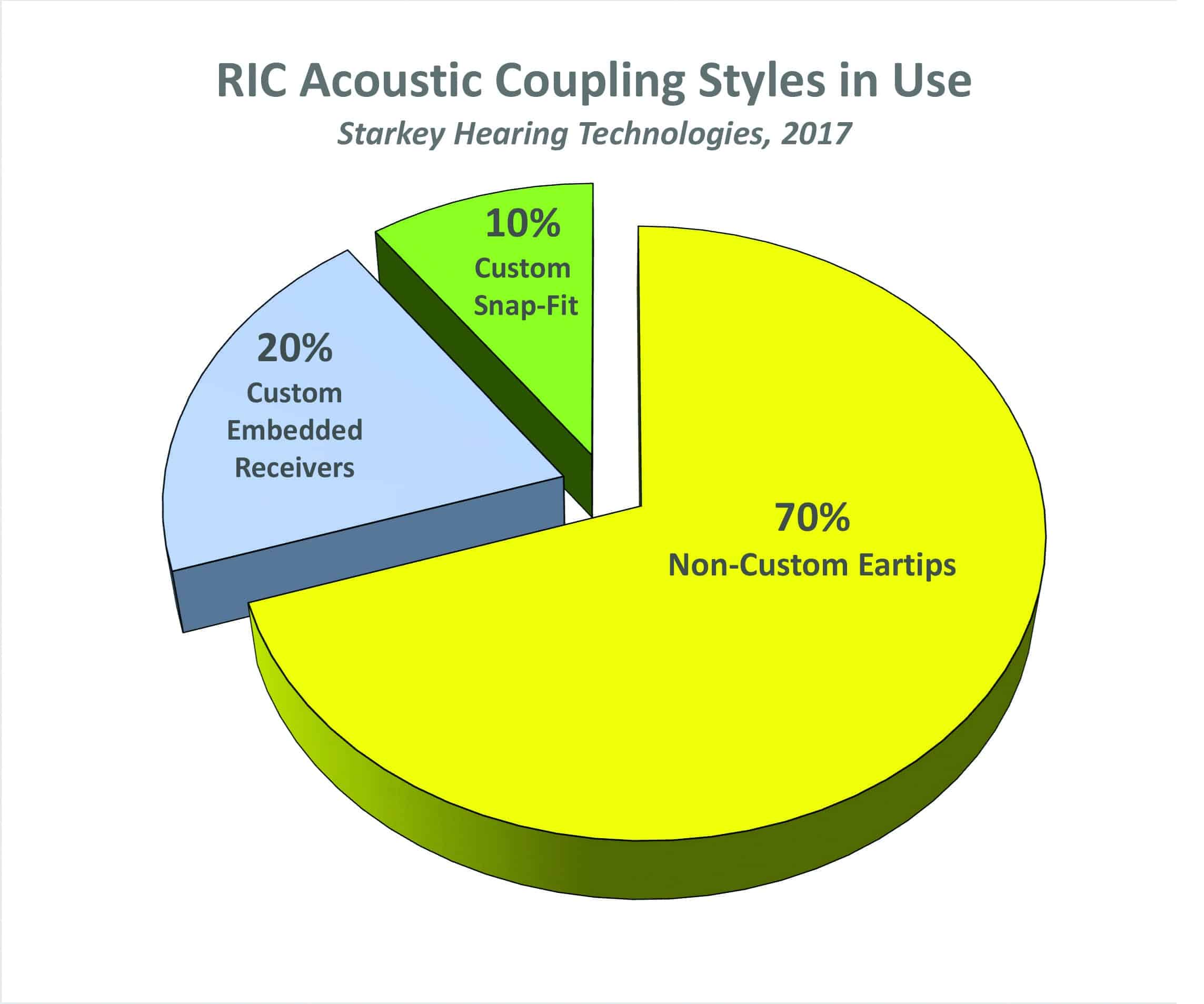
Figure 1. Estimate of RIC acoustic coupling styles in use. Source: Starkey Hearing Technologies (see text).
For the patient, over-the-ear hearing instruments require two distinct motor processes for effective use:
1) Placing the over-the-ear RIC body in the correct orientation (over and behind) the pinna, and
2) Inserting the receiver/acoustic coupling to the appropriate depth within the external auditory meatus.
Of these two actions, the latter can prove to be the most challenging skill for a patient to acquire—especially with stock eartips.
The degree of dimensional variability in the adult auditory canal is demonstrated in Figure 2, which was modified and reprinted courtesy of Wayne Staab, PhD. Superimposed on the graphic is a simulated RIC receiver with a stock eartip nominally inserted to the correct depth. The right angle of the RIC wire (dotted line) is flush with the aperture, providing optimal depth of insertion and orientation of the receiver with stock eartip.
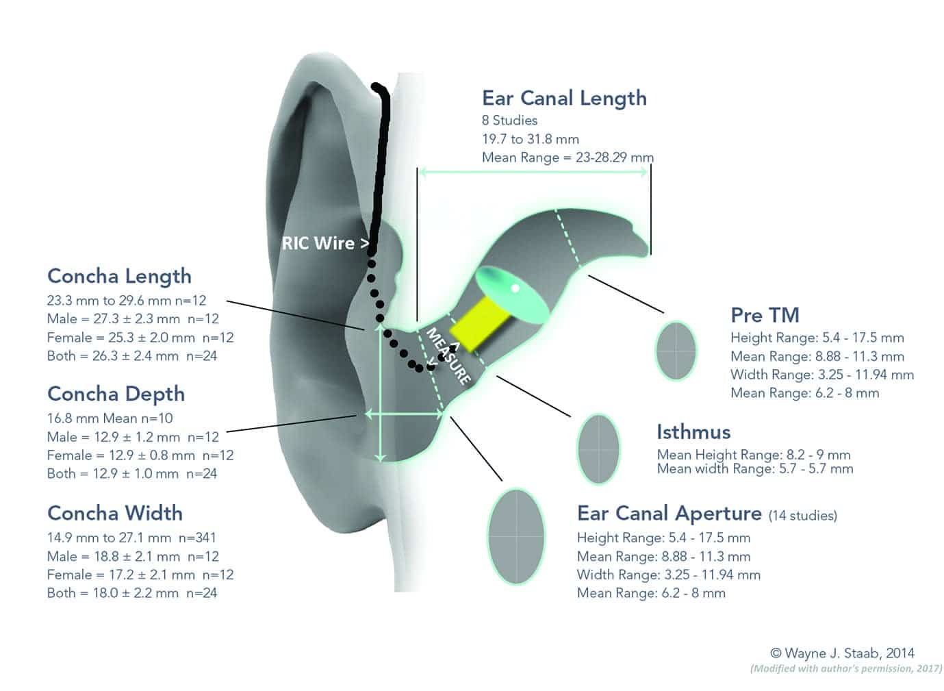
Figure 2. Dimensional variability of the external auditory canal. Courtesy of Wayne Staab, PhD,2 and adapted with permission.
In my clinical experience, most patients conceptualize the external ear as a tube perpendicular to the plane of the temporal area. In reality, medial to the aperture, the canal follows a sigmoid or crescent-shaped course in a postero-superior (behind and above) direction. The patient often experiences insertion difficulties when the RIC tip abuts the first bend of the ear canal.
Frequently, the dispensing professional’s insertion instructions suffer from a lack of common “frame-of-orientation” references. The patient functions in this process largely on the basis of tactile cues, and it takes training to envision proper orientation. A not-uncommon incomplete RIC insertion outcome is shown in Figure 3. Here one can see the instrument, as positioned, is at high risk for acoustical inefficiency, feedback, extrusion, or even physical loss.
A Simple Solution to Help Patients with RIC Insertion
The thin RIC wire, right-angled and not fully flush with the aperture, proves to be an elusive target for patient’s finger in attempting to further the insertion process to a secure depth. A simple method has been devised by the author to provide a temporary or permanent expedient to achieving consistently correct RIC receiver insertion. It entails the installation of a small piece of tubing over the standard RIC tubing so that the patient can use this tubing to help insert the hearing aid receiver (see Figure 7).
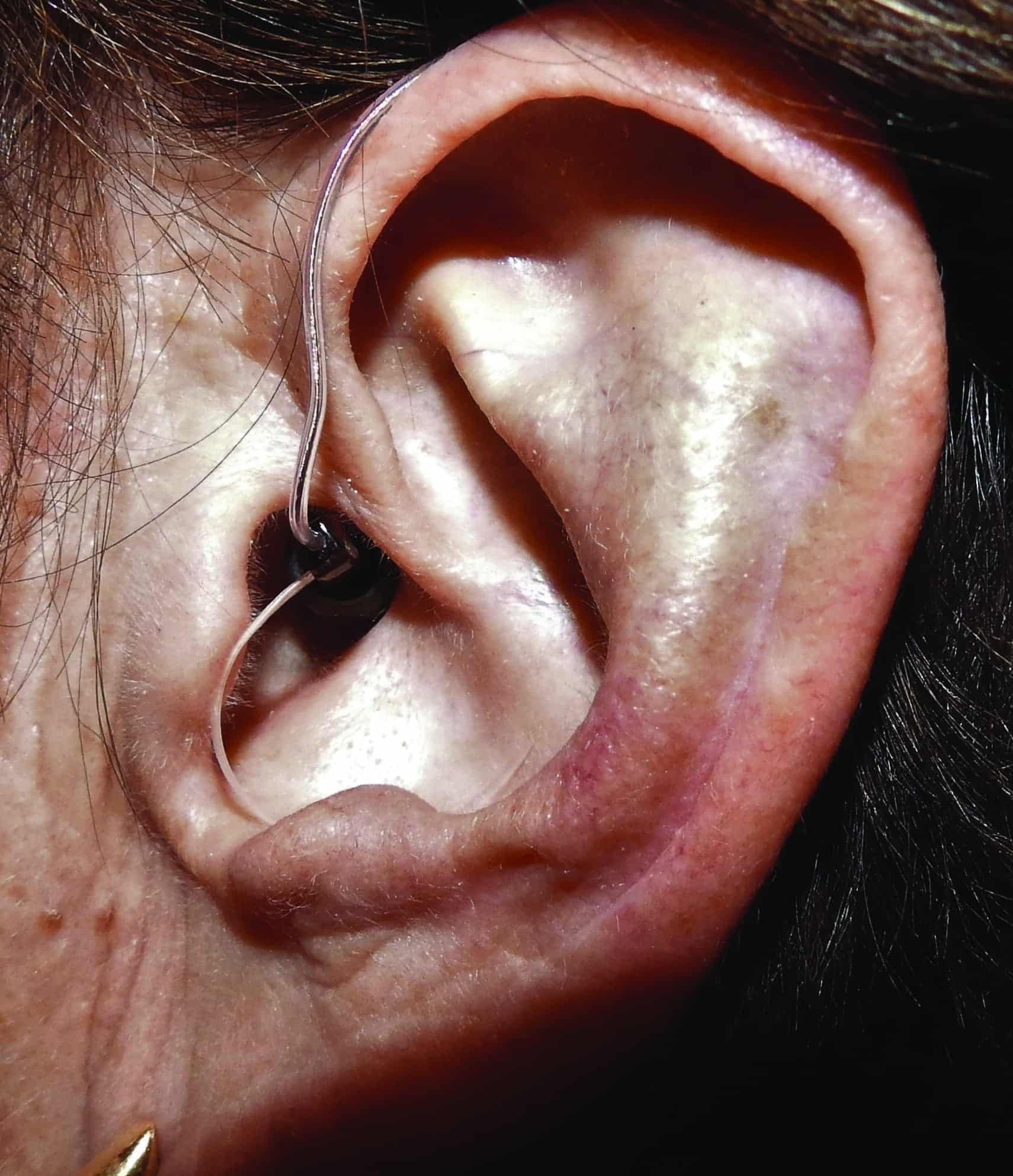
Figure 3. What we should be trying to avoid: a RIC at high risk for acoustic inefficiency, feedback, extrusion, and possible physical loss.
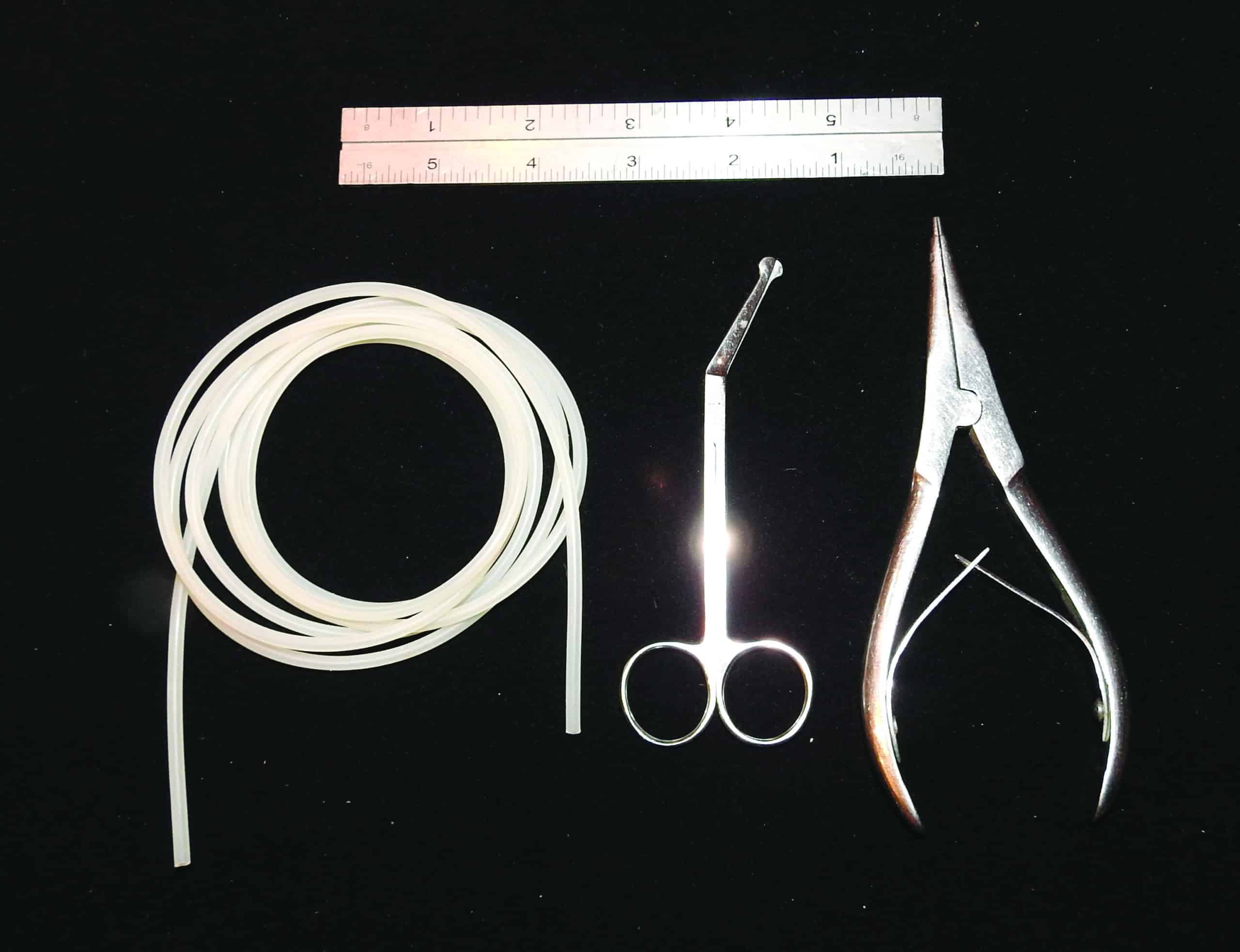
Figure 4. Tools and materials needed for the steps in this article.
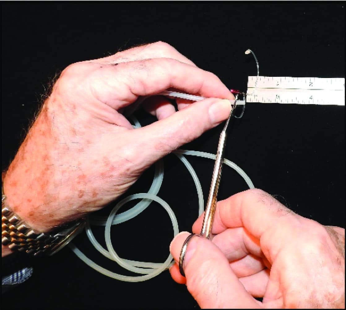
Figure 5. Cut a piece of 1/8-in od surgical tubing to the measured length (for narrower ear canals, you can use 3/16” od tubing).
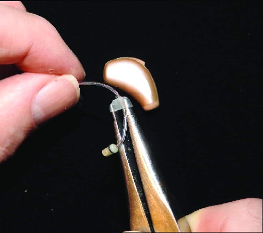
Figure 6. Mount the tubing segment on the earmold tubing expander.

Figure 7. Demonstrate to the patient this inconspicuous “training wheel”—which is actually a piece of tubing that helps them push the RIC into the ear canal.

Figure 8. The patient can place their fingernail at the bottom/front of the tubing placement and apply appropriate pressure to direct the receiver into the ear canal for full, secure insertion.
Figure 4 shows the necessary components: rolls of surgical grade 1/16” inside-diameter (id) / 1/8” outside-diameter (od) and 1/16” id / 3/16” od silicone tubing, ruler, surgical scissors, and earmold tubing expander.
1) Measure the distance from center of the receiver wire’s 90° bend to its insertion point at the RIC receiver housing (Figure 2).
2) Cut a piece of the 1/8” od surgical tubing to the measured length. For narrow diameter ear canals, begin with the 3/16” od tubing (Figure 5).
3) Mount the tubing segment on the earmold tubing expander and open the expander sufficiently wide to pass the RIC wire connector (Figure 6).
4) Reconnect the RIC receiver and slide the tubing segment flush with the lateral edge of the receiver housing.
5) Select the largest diameter of non-occluding or occluding stock tip that allows full insertion of the RIC receiver with comfort during full-time use.
6) Demonstrate to the patient the purpose of this inconspicuous insertion “training wheel” (Figure 7).
7) Instruct the patient to place a fingernail against the “bottom/front” of the tubing segment while applying gentle pressure. The receiver is then directed in the appropriate postero-superior orientation for full, secure insertion (Figure 8).
8) The tubing segment may be progressively shortened, removed or replaced with the narrower 3/16” od tubing when needed.
Conclusion
Consistently accurate RIC receiver placement in the auditory canal when using stock eartips results in optimally aided acoustical efficiency, minimized potential for acoustic feedback, and reduced extrusion and potential for instrument loss. The simple RIC receiver placement enhancement technique described here has worked well in my practice, providing a convenient and cosmetically acceptable answer to this significant clinical need.

Correspondence to HR or Dr Sullivan at: [email protected].
Citation for this article: Sullivan R. A simple and expedient method to facilitate receiver-in-canal (RIC) non-custom tip insertion. Hearing Review. 2018;25(3):12-13.
References
1. Strom KE. Hearing aid unit sales grow by 3.4% in 2017. January 17, 2018. Available at: https://hearingreview.com/2018/01/hearing-aid-unit-sales-grow-3-4-2017/
2. Staab W. Ear canal dimensions. July 14, 2014. Available at: http://hearinghealthmatters.org/waynesworld/2014/ear-canal-dimensions/