Delay and phase problems could be one of the “invisible” differences between patient satisfaction with binaural (as well as vented monaural) hearing instruments and rejection of amplification. As signals are processed electronically through hearing instruments, manipulated by complex algorithms, then presented to the ears of listeners, it’s possible for substantial phase mismatches in the signals to occur relative to either the sound coming from a partially open earmold or the other hearing aid in a set of binaural aids. This article examines a method of measuring this phase delay, as well as a test that allows one to tell if a hearing instrument is analog or digital.
Digital hearing instruments have burst onto the scene as the solution for many fitting problems. The digital approach works. It is certainly possible to incorporate many types of signal processing operations into the tiny silicon wafer that is at the heart of any digital hearing aid.
There are, however, some interesting side effects that occur when the digital approach is used. These effects might be compared to those side effects that can occur when a powerful new drug is prescribed; some of the side effects can be undesirable, while others do not affect the intended result. This article outlines an effect called the processing delay (or group delay) and a way to measure it so that hearing care professionals can make informed decisions during a fitting.
Another effect that can be found in both analog and digital products is a potential culprit in the failure of some binaural fittings. It relates to the “phase” of the sound coming from the hearing instrument. This side effect and one method of measuring it are also described here.
Hearing Aid Electronics 101
The dispensing professional is quite used to handling hearing instruments with analog circuits, including those that are controlled by digital programming systems. An analog hearing instrument uses a transistor amplifier to operate on the incoming electrical signal from its microphone. The amplifier then passes this signal onto the receiver to make it loud enough for a person with a hearing impairment to hear (and hopefully interpret) the sound comfortably.
Analog hearing aid amplifiers can be arranged in a number of ways, but all require transistors, resistors and capacitors. While it is possible to place a large number of transistors and resistors on the small silicon chip of a hearing instrument, relatively bulky capacitors are still needed to make analog circuits. Size constraints are getting more confining as hearing instruments continue to get smaller. For example, the capacitors take up a considerable amount of the available space in a completely-in-the canal (CIC) hearing aid.
As discussed in a previous article by the author1, the circuit in a digital hearing instrument has a different mode of operation. The analog electrical signal from the microphone is passed to a device that transforms the signal into a series of numbers. This is necessary because digital circuits work on the binary (“0” and “1”) system, not analog amplitudes. The numbers are then added, subtracted and manipulated by mathematic functions for the processing of the signal. Once the processing is completed, the series of numbers are converted back into an analog signal and delivered to the ear through a receiver.
The method that the circuit uses to work on the signal numbers is called an algorithm. There are many different forms of hearing aid algorithms. Some are more efficient than others. Some by their nature require the capturing of large sets of numbers in order to make spectral determinations of the incoming signal. The conversion of these sets back into an analog signal is also necessary to produce a replicated version (i.e., a signal that is corrected for the hearing loss) of the original sound.
Even though it is performing a good deal of signal processing, the digital hearing instrument needs fewer capacitors compared to an analog hearing instrument. It also needs fewer circuit components. This gives digital aids a distinct mechanical advantage. Unfortunately, there are some other factors that complicate matters.
Effect 1: Processing or Group Delay Time
The time taken in the amplification and frequency shaping process of an analog hearing instrument is relatively short—on the order of a few tenths of a millisecond (ms). In analog hearing aids, the time taken for the sound to travel down the “plumbing” of a behind-the-ear (BTE) hearing instrument is probably longer than the time the electrical signal takes to get through the amplifier.
It is a different matter with digital hearing instruments. It takes a significant amount of time for a digital circuit to add and subtract the numbers called for in its algorithm. This amount of time depends on the algorithm used and the amount of spectral processing that is done. All digital designs are different. The time taken for number processing can vary from as little as 1 ms to as much as 10 ms. In general, the more signal processing done, the more time used in processing numbers. This statement does not take into account a number of factors, including the efficiency of the algorithm, the speed of the processor and the use of specialized digital hardware to handle the calculations.
Effects of the Digital Processing Delay: Is this delay important? Can it cause hearing intelligibility problems? If sound can reach one or both ears through more than one path, then echo effects may be found. Echoes and reverberation in a room adversely affect intelligibility and are normally considered to be undesirable. The same can be said of artificial echoes generated by delay in a hearing instrument. If a digital hearing aid is fitted to only one ear, or if the aided ear is fitted with a non-occluding earmold, then the possibility exists for sound to arrive at the aided eardrum via more than one path and at different times. A digital processing delay of more than a millisecond may be important in a case such as this.
On the other hand, it may be safely stated that, if two identical digital hearing aids are fitted binaurally with occluding earmolds, the only sound that reaches the ears is through the digital hearing instruments. In this case, the processing delay will not add disturbing artifacts to the sound delivered to the ears.
Measurement of Processing Delay: Because of a number of recent experiences and demands, the engineers at Frye Electronics have developed a special option for the 6500CX test instrument that allows the professional to directly measure the processing delay of a hearing aid.
Built into a coupler and sound-chamber-based utility known as the “Star option,” the test is accessed by pressing the asterisk button after setting up the option menu to run the Enhanced DSP test. The measurement uses a simple broadband impulse and a 20 ms time window.
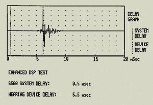
An example of the processing delay in a hearing instrument is displayed in a graph of voltage vs. time and also as a number in Fig. 1. The 5.5 ms delay shown in the figure represents the actual processing delay measurement (in milliseconds) made on a popular digital hearing instrument. It is calculated from several factors, including the sampling rate of the analyzer (25.6 kHz), the internal analyzer system delay (0.5 ms typical) and the characteristics of the signal coming from the hearing instrument. As a comparison, a test of an analog hearing instrument is shown in Fig. 2. The time delay through this AGC analog circuit was measured at 0.5 ms, or less than one-tenth that of the digital circuit.

|
| Fig. 1. Measurement of the processing or group delay of a digital hearing instrument. |

|
| Fig. 2. Measurement of the processing or group delay of an analog hearing instrument. |
Effect 2: Amplification Phase
A hearing instrument delivers sound to the ear by means of an electrical drive to the receiver. This drive can be delivered in a way in which the sound is in phase with and adding to the sound arriving at the ear. Alternatively, it can be out of phase or opposing that sound. There may be good reasons for designing a hearing instrument either way. But if a binaural set of hearing instruments is placed on a hearing-impaired listener, the phase of these two amplifiers needs to be matched, especially if the ears on which they are fitted have similar impairments. This statement applies equally to digital and analog hearing instruments.
|
Is This Hearing Aid Analog Since all types of hearing instruments (e.g., CICs, ITCs, BTEs, etc.) are now produced in both analog and digital models, it is often quite difficult to determine the construction of a “mystery” hearing aid that a patient brings into the office. Physical examination and normal electroacoustic analysis may not give the clues to its design. New tests offered by test instrument manufacturers are making this task increasingly easier. For example, Frye’s Enhanced DSP test is designed to provide dispensing professionals with information on an instrument’s processing characteristics. One fairly safe assumption is that, if the hearing instrument has a processing time of greater than one millisecond, then it is probably digital. Using this generalization, a dispensing professional can infer if a hearing instrument is analog or digital.
An example of a series of tests run on an unknown ITE hearing instrument is shown in Figs. 3 and 4. The ANSI S3.42-1992 analysis2 (the ANSI 92 option in the 6500CX) shows that it is behaving as a simple linear circuit (Fig. 3). In this test, a series of gain curves are collected at a number of different input sound levels (in this case, 50, 60, 70 and 80 dB SPL RMS). The gain curves of the hearing instrument all lie on top of each other, showing that no AGC action was occurring, at least for this range of input or output levels. The input/output (i/o) curve is also a relatively straight line at a 45° angle. This indicates that, for 10 dB of input signal increase, the output also increased by 10 dB until the circuit saturated above 80 dB SPL.
A test of this hearing aid (Fig. 4) shows that it has a processing delay of 3.4 ms, which is a good indicator that this “simple linear” hearing instrument contains a digital processor. Is this a bad result? Not necessarily; if the hearing instrument were unknown to the hearing professional, it may be a surprising result for a digital product. If the aid were fitted by the professional as an AGC aid, the linear action seen in the ANSI S3.42 test sequence may also have been surprising. w |


A person with near-normal hearing who has access to a stereo audio system with detachable speakers can easily demonstrate the effects of mismatched phase. The speakers in these systems typically have color-coded connectors that are intended to be connected through wires to similarly color-coded terminals on the power amplifier. Stereo effect is present if the connections are made properly. A simple phase reversal test can be made by temporarily swapping the ends of the wires on only one of the speakers. When that is done, the stereo effect is lost and the sound quality is notably degraded.
The same degradation in quality is heard when the “wiring of the receivers” in a binaural pair of hearing instruments is not matched. This problem is probably more often seen in custom hearing instruments, where the receivers are hand-wired to the amplifiers. It is quite possible that this phenomenon accounts for a number of rejected fittings where all the numbers add up but the patient is still unhappy with the result.
Measurement of Amplification Phase: A phase test is built into the same testing option described in the sidebar. The test is performed simultaneously with the processing time delay test, and the results are shown in a 20-ms window on a different screen. The test pulse is different, being wider and shaped to test the response of the hearing instrument to frequency components at 1000 Hz and below (Fig. 5). The sound box itself is tested in this figure, with the natural 100 Hz resonant frequency of the speaker causing a ringing, following the 1-ms wide cosine impulse.

|
| Fig. 5. Phase test pulse waveform. |

|
| Fig. 6. Phase inversion construction example for a matched binaural pair of hearing instruments. |

|
| Fig. 7. Mismatched binaural pair of hearing instruments. |
A phase test for a binaural pair would be run on one hearing instrument at a time. The test results for the first aid are printed, and then the second aid is tested and its results printed. The printouts are then compared for proper phase. Tests for two matched but otherwise reversed hearing instruments would appear as in Fig. 6. This set of graphs was constructed as an example of what would be seen in a mismatched pair. They do not represent an actual set of tests. The mismatch is easily seen and is to be avoided.
Delay times and transient behavior of a pair of digital hearing instruments should also match. Fig. 7 provides a less-than-ideal set of responses for an actual pair of digital hearing instruments. The transient behaviors of the two are different and could cause listener confusion. It should also be noted that the time delays of the two are slightly different.
This begs several interesting hypothetical questions, including, “What if a client (for whatever reason) wants to wear two different models of hearing aids as part of a binaural fitting” (e.g., keep one old aid and purchase one new aid). While this is probably rare (and inadvisable), common sense would suggest that the dispensing professional first run a delay/phase test to ensure that the instruments were compatible in terms of the phase measurement.
Summary
Any particular hearing instrument—whether analog or digital—is a device that behaves exactly as it should: it obeys the laws of physics. Unfortunately, that behavior may not be exactly what the hearing care professional wants or expects.
New tests have been designed to provide the hearing care professionals with more tools, helping to demystify some of the processing that underlies the performance of modern hearing instruments. Delay and phase problems could be part of the “invisible” differences between patient satisfaction and rejection of amplification. Ultimately, it is hoped that the benefit achieved through the use of these tools will lead to better fittings, and encourage more hearing-impaired people to search for better hearing through amplification.
|
Correspondence can be addressed to HR or George J. Frye, 9826 Tigard St., Tigard, OR 97281-3391; email: [email protected].
References
1. Frye GJ: A Perspective on Digital Hearing Instruments. Hearing Review 1999; 6(10): 61.
2. Acoustical Society of America (ASA): American National Standard Testing Hearing Aids with a Broad-Band Noise Signal (ANSI S3.42-1992): New York City: ASA, 1992.