Old-school acoustic plumbing principles for today’s instant-fit mini-BTEs
We can exploit the rules of earmold acoustics to our advantage, even with thin tubes. We just need to understand what is going on acoustically at the eardrum, and this knowledge is obtained through probe microphone measurements.
The cosmetic appeal of thin-tube fittings has encouraged more people to seek assistance for mild and high frequency hearing losses, and they may be doing so at an earlier age. The open-canal configuration commonly associated with thin-tube fittings has also meant a higher level of satisfaction with amplification than was previously the case for these types of hearing losses due to relief from the occlusion effect.
However, the success of thin-tube fittings in this target demographic has led to a tacit assumption among some clinicians that candidacy for a thin-tube fitting with a small BTE is limited to individuals with mild and/or high-frequency hearing losses. For hearing losses outside this range, traditional custom and BTE hearing aid fittings can deliver excellent benefit and satisfaction, especially since digital signal processing has made it a relatively simple matter to significantly alter the electroacoustic characteristics of a fitting.

|

|

|
| Darrell E. Rose, PhD, is the former audiology section head at the Mayo Clinic, Rochester, Minn, and is a retired audiologist who continues researching and consulting. Robert M. Ghent, Jr, MS, is a senior research audiologist with Sonic Innovations, Salt Lake City. Nick Wright, BC-HIS, is a hearing instrument specialist in Lehi, Utah. | ||
Nevertheless, many individuals who would benefit from traditional custom or BTE hearing aids find the cosmetic appeal of a thin-tube fitting a much more attractive alternative. The goal, therefore, is to find ways to extend candidacy for thin-tube fittings to these individuals.
In order to accomplish this, thin-tube fittings need to deliver sufficient gain and output across a broad enough frequency response to compensate for a variety of audiometric profiles. These should include flat hearing losses, as well as moderate hearing losses in the highest speech frequencies (>4000 Hz).
Accomplishing these goals requires much more low- and mid-frequency gain and output than are typical for most thin-tube fittings, plus a well-controlled, extended high-frequency response. However, achieving these results is inherently difficult: Given the target demographic, the prevalence of open canals with thin-tube fittings means that a significant amount of low- and mid-frequency acoustic energy is lost to the environment. Additionally, since long, thin tubes impede the passage of high frequency acoustic energy, the use of a thin tube is contraindicated for extended high frequencies, and much of the high frequency energy that is successfully pushed through a thin tube is lost with open-canal fittings as well—a situation that also increases the risk of acoustic feedback.
Because they are so cosmetically appealing and comfortable, it is tempting to try to fit thin-tube devices using the supplied domes on hearing losses that are outside their recommended fitting range. Initial findings with such fittings (unpublished data, Darrell Rose) revealed that, although the instruments were readily accepted, individuals with even a mild low frequency loss often returned for the follow-up visit with a significant complaint of “I love the way this aid feels. I don’t have the plugged feeling that I had with my other aid, but I really don’t hear as well as I thought I would.” Upon attempting to obtain additional gain and output from the instrument, acoustic feedback became a problem. Even with the more occluding “tulip tip” dome and a robust feedback cancelling algorithm, it is often not possible to obtain adequate gain for many fittings.
Such was the impetus for a previous article by Rose1 that showed the possibility of obtaining considerably more gain and output, and a varied frequency response, by using a custom earmold with a thin tube. However, the use of a custom earmold defeated the significant advantage of the typical thin-tube fitting procedure that allows for an immediate fit, trial, and sale of the instrument. The domes supplied by manufacturers of thin-tube devices allow for individuals to try the instrument in the office and purchase it on the spot without the need of waiting for ear impressions to be sent off and earmolds to be returned before the purchaser could obtain the aid. Nevertheless, the open domes, and even the tulip tip, limit the candidacy for thin-tube devices.
The purpose of this article is to examine a number of acoustic plumbing modifications that can be used with the thin tube to extend candidacy for these devices. The degree of flexibility and control available through fitting software for digital hearing aids has allowed most clinicians to become quite facile with making appropriate electro-acoustic adjustments, but these are effective only if the acoustic energy from the hearing aid is actually available at the eardrum.
Clinicians need to remember the flexibility and control available from acoustic adjustments to the circuit formed by the interaction of the ear canal and the plumbing of the sound delivery system. Old-school earmold acoustics may seem archaic compared with the frequency-shaping resolution of modern multichannel compression amplifiers; however, should one violate the simple rules of earmold acoustics, it becomes difficult to overcome fitting problems—even with the most sophisticated signal processing and software.
On the other hand, we can exploit the rules of earmold acoustics to our advantage, even with thin tubes. We just need to understand what is going on acoustically at the eardrum, and this knowledge is obtained through probe microphone measurements.
A review of the early work on earmold acoustics and modifications suggests that the same science should apply to thin-tube fittings. One need only consider the effects of a much smaller diameter tube in the acoustical coupling, along with the technological advances in output transducers, signal processing, and software control. The balance of this discussion illustrates the use of various modified tips to alter thin-tube acoustics in controlled and predictable ways, based on known behaviors from these early studies of earmold acoustics. (While a comprehensive list of citations is far too voluminous to be included here, the reader is referred to Killion2 and one of the textbook chapters by Lybarger,3 Leavitt,4 or Pirzanski5 for a solid grounding in the history, physics, application, and modification of conventional earmolds, as well as myriad topical references.)

|
| FIGURES 1a-b. Left: High-frequency loss audiogram used to generate fittings for the measurements obtained for this article. Right: Flat audiogram used to generate fittings for the measurements obtained for this article. |
The aim of this article is to introduce some acoustic modifiers to be used exclusively with thin-tube fittings that would:
- Be comfortable;
- Sufficiently obstruct the ear canal slightly past the second turn in an effort to reduce the occlusion effect;
- Allow for greater gain and output in the low to middle frequencies;
- Extend the high-frequency response; and
- Markedly reduce the propensity for feedback.
More High-Frequency Energy

|
| FIGURE 2. Comparison of an open dome (blue curve) and a horn tip (red curve) on a high-frequency audiogram thin-tube fitting. Everything else being equal, the horn provides a slightly extended frequency response and more high-frequency gain and output. While the open dome fitting is probably adequate compensation for the audiogram in Figure 1a, the horn may be more efficient at achieving the same end. |
Without going into details about the acoustic principles involved, we will begin by looking at the effect that various thin-tube tips have on fittings derived from the audiograms for a high-frequency hearing loss and a moderate flat hearing loss, as shown in Figures 1a and 1b.
The reader should bear in mind a few caveats during the subsequent discussion. The fittings are generated by the proprietary fitting algorithm developed for the Velocity miniBTE hearing aid (Sonic Innovations Inc, Salt Lake City) and used in the measurements, and the fitting algorithm compensates for the effects of a thin tube relative to using standard #13 tubing with an earmold. Also, all of the measurements are probe microphone measurements obtained on a KEMAR right ear with the loudspeaker positioned at 45° azimuth. For the purposes of this discussion, all of the probe microphone curves are presented as REAR in dB-gain rather than dB SPL (ie, the input level has been subtracted out) in order to compare relative magnitudes. Finally, feedback cancellation was not used with any of these fittings. (Readers interested in more details about these probe microphone measurements, or the acoustical foundations on which this article is built, should contact the second author for a copy of the presentation6 from which much of this information is derived.)

|
| FIGURE 3. Detail of Synygis thin-tube horn tip (patent pending). |
Figure 2 compares a typical open dome and an acoustic horn modifier used with a thin-tube fitting for the high-frequency audiogram in Figure 1a, and demonstrates an additional 3 dB or so of high-frequency output, and a slightly extended frequency response available by taking advantage of the “horn effect,” a well-known technique for increasing high-frequency energy in conventional earmold fittings that has been used for decades.
The patent-pending horn tip used in this example (Figure 3) was supplied by Synygis (Plano, Tex). Use of a high-frequency modifier, such as this horn, capitalizes on the fact that high-frequency energy is still present from the hearing aid, although it is attenuated by the thin tube. The horn serves as an acoustic impedance transformer at high frequencies, allowing energy at these frequencies to be restored somewhat at the output of the horn. As the purpose for this article is a simple demonstration of the principle, calculations of the horn cutoff frequency and ideal “flare ratio” were not undertaken.

|
| FIGURE 4. Comparison of an open dome (blue curve) and a tulip tip (orange curve) on a thin-tube fitting for the flat audiogram in Figure 1b. Necessary middle-frequency energy cannot be retained in the ear canal with the open dome. While the tulip tip dome retains more energy at these frequencies, it still may not be adequate to compensate for the hearing loss. |
|
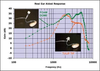
| FIGURE 5. Comparison of a tulip tip (orange curve) and a foam dome (green curve) on a thin-tube fitting for a flat audiogram. The foam dome retains significant lowand middle-frequency energy in the ear canal without feedback, sufficient to compensate for the flat audiogram in Figure 1b. Also note the large high-frequency advantage of the foam dome’s combined horn effect and deep placement |
One caveat with this modifier when used with an open ear canal is the increased risk of feedback, but it does work well with an excellent feedback cancelling algorithm. The curves in Figure 2 were obtained without a feedback canceller enabled, and the only difference between them is the open dome versus the horn tip. Since the fitting software can control frequencies above 4,000 Hz, it is conceivable that even greater increases are possible if the feedback canceller is engaged.
More Low- and Middle-Frequency Energy
As discussed, when considering flat audiograms, it is not possible to retain adequate acoustic energy in the ear canal at the low and middle frequencies with the open dome. This is illustrated by the blue curve in Figure 4. The tulip tip is designed to replace the open dome in fittings where more gain and output are required than are possible with the open dome. The orange curve in Figure 4 demonstrates that, while the tulip tip does retain more energy in the ear canal than the open dome, the fitting may still be inadequate to compensate for the flat audiogram in Figure 1b.
In this case, it is necessary to completely occlude the ear canal in order to retain all of the acoustic energy delivered by the hearing aid. We selected a product developed by Hearing Components (Oakdale, Minn) to demonstrate what can be achieved by occluding the ear canal and creating a small residual volume between the medial opening of the thin tube and the eardrum. Figure 5 compares the results using the tulip tip with the flat-audiogram fitting (again in orange) to those obtained with a Comply™ Foam Dome (aka T-tip as shown in Figure 6) on the same fitting parameters (green curve). There is now, on average, a 15 dB increase in low- and middle-frequency gain and output, making this thin-tube fitting more suitable for flat audiometric hearing losses.
One may notice from the curves in Figure 5 that, in addition to the improved low- and middle-frequency performance, there is an extraordinary high-frequency advantage using the foam dome. This results from two factors: 1) The foam dome provides a horn effect, not unlike that obtained with the horn tip, because the tube diameter transitions from 0.8 mm to 1.9 mm, and 2) the deep insertion of the foam dome creates a small residual volume, increasing the sound pressure level for high frequencies, as well as for the low and middle frequencies. The foam dome could conceivably be used for very high-frequency fittings, as well as flat fittings, in which case the occlusion effect must again be considered.

|
| FIGURE 6. Detail of Hearing Components’ Comply Foam Dome or T-Tip. |
In real ears, positioning the foam dome just medially to the second turn of the ear canal should help minimize the occlusion effect and seal the ear canal, thereby ameliorating feedback as well, but patients may complain of irritation from such deep placement. This was borne out in a few of the subjects who tried the foam dome. It is not easily placed deep in the ear canal, so additional sizes are required. Also, it is necessary to adjust the length of the foam dome tubing. This is easily accomplished with tools typically used to adjust the length of conventional earmold tubing, but setting the correct depth of the foam dome is not trivial.
Summary
With just a limited set of examples, we’ve seen how the science of earmold acoustics not only holds up, but can be exploited in thin-tube fittings to extend the fitting range, and therefore the candidacy, for hearing aids that are conventionally thought to be for individuals with high-frequency hearing losses. Tips for use with thin tubes, in addition to the “open” and “tulip tip” domes, can provide additional high-frequency output. These techniques can also extend the frequency response, or can significantly increase gain and output in the low and middle frequencies without exacerbating feedback or the occlusion effect.
When the acoustic principles demonstrated herein are used with mini-BTE or micro-BTEs that can be converted between thin-tube and conventional earhook configurations, clinicians have an impressive range of fitting flexibility in a single, cosmetically desirable instrument with which to introduce the benefits of amplification to a wider population.
References
- Rose D. The return of the earmold. Hearing Review. 2006;13(9):14-19.
- Killion M. Earmold options for wideband hearing aids. J Speech Hear Disord. 1981;46:10-20.
- Lybarger S. Earmolds. In: Katz J, ed. Handbook of Clinical Audiology. 3rd ed. Baltimore: Williams & Wilkins; 1985:885-910.
- Leavitt R. Earmolds: acoustic and structural considerations. In: Hodgson WR, ed. Hearing Aid Assessment and Use in Audiologic Habilitation. 3rd ed. Baltimore: Williams & Wilkins; 1986:71-108.
- Pirzanski CZ. Earmold acoustics and technology. In: Sandlin RE, ed. Textbook of Hearing Aid Amplification. 2nd ed. San Diego: Singular Publishing Group/Thomson Learning; 2000:137-169.
- Ghent R, Rose D. Open canals and thin tubes: acoustical mystery tour. Instructional course presented at: AudiologyNOW! 20th Annual Conference of the American Academy of Audiology; April 2008; Charlotte, NC.
Correspondence can be addressed to HR at [email protected]; Darrell E. Rose, PhD, at ; or Robert M. Ghent, Jr, MS, at .