Directional instruments remain the surest way to increase the signal-to-noise ratios (ie, enhancing hearing in noise) for hearing aid wearers. The most common method for quantifying the directionality of a hearing aid is through the use of the directivity index (DI). Unfortunately, there are essentially three different ways in which DI can be expressed. For example, if one manufacturer uses theoretical values for its DI, and another uses KEMAR-derived DI values, the results will generally favor the former, even though the latter manufacturer is using more accurate values. This article describes the differences between the various uses of the term “DI.”
Directional microphones have found renewed acclaim in the world of hearing aids. With the myriad of options available (one- and two-mic designs, different/multiple polar patterns, automatic and adaptive functions, etc) the dispensing professional often looks to the manufacturer to provide some evidence of design superiority.
The directivity index (DI) is typically used to quantify the directional characteristic of the various products. Unfortunately, the term is often used to refer to other directional characteristics, such as front-to-back ratio or best ratio of front-facing signals relative to sound sources occurring at alternate azimuths. This misinformation has led to confusion in many clinical attempts to understand differences between products. In this brief article, several issues related to measuring and reporting DI will be addressed. Authors’ Note: While we will be citing the mathematical formulas used to describe directivity, the reader should concentrate not so much on the formulas themselves; rather, it is important to recognize what components of directivity these formulas consider.
The measurement of directivity has been commonly applied in other disciplines for over 60 years. The generally accepted formula from Beranek1 (1954) is shown in Equation 1, where…
Equation 1:

- [pax]2 is the magnitude of the on-axis mean-square sound pressure microphone response to a plane-wave signal in free field, and
- [p(ø,ð)]2 is the magnitude of the off-axis mean-square sound pressure microphone response to a diffuse sound field.
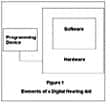
Essentially, this equation describes DI as being the on-axis response (Pax) of a directional microphone system to sound in contrast to its off-axis response (P(ø,ð). Using a Cartesian coordinate system, “on-axis” typically is defined as the direction perpendicular to the faceplate of a microphone when measured in a free-field environment (Figure 1). This also holds true for microphones housed in hearing aids and measured in free field (Figure 2).
.gif)
Figure 1. On-axis position of microphone in free field is aligned with the x-axis.
.gif)
Figure 2. As in the previous figure, on-axis position of a hearing aid microphone in free field is also aligned with the x-axis.
When the hearing aid microphone system is moved from a free-field measure to a measure using a manikin (eg, Knowles Electronics Manikin for Acoustic Research or KEMAR), the on-axis position of the microphone remains positioned in a free-field measurement condition. The head, pinna, and torso will have an affect on the directivity of an in-the-ear (ITE) or behind-the-ear (BTE) hearing aid microphone system As a result, this has led some to adjust the on-axis response of the microphone to reflect either an average response in reference to signal presentations from multiple directions or a response of maximum sensitivity to a signal presentation other than at 0° (eg, 80° azimuth for a BTE).
Equation 2:
Off-axis response of a microphone (ie, the [P(ð,ø)] portion of the equation) is the response of the microphone to sounds arriving from all possible directions. This integral-derived response is commonly computed by a summation approximation (Equation 2). The amount of spatial information required for a reliable summation approximation depends on the symmetry present in the device under test. For a free-field measure, an off-axis response from systematic signal presentations is sufficient (Equation 3). However, when computing the off-axis response of a microphone on KEMAR, further spatial information is required.
Equation 3:
Since virtually all hearing aids are worn on heads (rather than dangling from an anechoic chamber ceiling), it is necessary to consider the differences in measurement that would result from those different environments. In addition, it may be of interest to ascertain the mathematically ideal DI, based on the available polar patterns. Therefore, we have measured the DI of microphones using both Equations 2 and 3 in our lab.
DI in the Real World
A common misconception in DI computations involving a manikin is the assumption of symmetry between the horizontal and vertical planes (Equation 3). This issue is addressed throughout the literature in a number of respected, peer-reviewed articles.2-4 One cannot assume such symmetry with a manikin present in the sound field, and we have shown that it does not exist. Not only is there asymmetry found in a manikin and hearing aid combination, the hearing aid style also impacts the DI measure due to the placement location of the microphone and the change in the acoustical environment because of head, pinna, and torso reflections.
Since the DI can be empirically derived from free-field and KEMAR measurement conditions, as well as computed from the mathematically ideal situation, we are now presented with a situation in which three different DIs can be reported for the same directional device. The first, which we will term Theoretical DI, is a mathematically-derived DI average computed from the theoretical spatial directivity pattern associated with the directional microphone hearing aid (DMHA). In other words, a DMHA is said to have a directional microphone that models a specific spatial directivity pattern (eg, cardioid). The spatial directivity pattern, with its associated mathematical description, is then used to calculate the DI.
The second, which we will term Free-field DI, is an empirically-derived DI average computed from spatial measurements of the DMHA suspended—in isolation—in a free-field environment (eg, anechoic chamber). Thus, microphone mass and frequency domain characteristics of the DMHA are taken into consideration in this approach of computing the DI. This is a more realistic estimation of the DMHA’s DI because, within and across hearing aid manufacturers, DMHA free-field DIs can vary by 3 dB or more for microphones modeling the same spatial directivity pattern.5
The third, which we will term KEMAR DI, is an empirically-derived DI average computed from spatial measurements of the DMHA on a manikin in a free-field environment. This is similar to the free-field DI except that it takes into consideration the average effects of head, torso, and pinna on DMHA directivity. A manikin, such as KEMAR, is used so as to represent the average dimensions of an adult head and torso.6
Data collected over the last 4 years covering numerous manufacturers and hundreds of hearing aids are provided in Table 1. Here, one can observe differences between the theoretical, free field, and KEMAR DI averages for different polar patterns and different hearing aid styles. As the sound field becomes increasingly complex around the directional microphone, a reduction in DI is noted (eg, Free-field DI versus KEMAR DI).
|
||||||||||||||||||||||||||||||||||||||||||||||||||||||
| Table 1. Theoretical, free-field, and KEMAR unweighted average DI values for 1st and 2nd order directional microphones in ITE and BTE hearing aids. Second-order directional microphones consist of more than two ports; end-fire refers to an array design that is separate from the hearing aid case. KEMAR DI computed via equation 2. | ||||||||||||||||||||||||||||||||||||||||||||||||||||||
This approximate 3 dB DI reduction from the ideal theoretical DI and the KEMAR DI is also evident across 1st and 2nd order directional microphones. It is important to note that KEMAR DI estimates must be derived from Equation 2, which assumes no horizontal or vertical symmetry. If the KEMAR DI is computed from Equation 3, this represents only a single plane and assumes horizontal and vertical symmetry exists in KEMAR (eg, the shape of a ball). A DI estimate using Equation 3, depending on whether it is from an ITE or a BTE DMHA, may be 1-2 dB DI higher than the more spatially-representative method found in Equation 2.7 The authors are currently working on a study designed to estimate the “true” directivity index for hearing aid first-, second-, and higher-order directional microphone systems in free field and on a KEMAR.
Summary
Three derivatives of DI may be presented for the same directional instrument. This is important to understand, especially when comparing different directional technologies. For example, if Manufacturer A uses the theoretical values for DI in its specifications, and Manufacturer B uses KEMAR-derived values, Manufacturer A will appear to produce a better product, although Manufacturer B has provided a more accurate value.
If hearing care professionals are to have some means of comparing the directional characteristics across products, such reporting should either become standardized, or the manufacturers need to provide additional information relative to how the measurements were obtained. The current ANSI working group has determined that any measure obtained other than by the use of Formula 2 (ie, assumption of no vertical symmetry) must be so noted. In other words, if a KEMAR DI is used by industry to represent the directivity of a product, Equation 2 must be applied in order to obtain an accurate estimate of its true directional characteristics.

|
Correspondence can be addressed to HR or Andrew Dittberner, PhD, University of Northern Colorado, 1480 Gunter Hall, Greeley, CO 80631; email: [email protected].
References
1. Beranek LL. Acoustics. New York: McGraw-Hill Electrical and Electronic Engineering Series, McGraw Hill; 1954.
2. Fortune TW. Real-ear polar patterns and aided directional sensitivity. J Amer Acad Audiol. 1997;8:199-31.
3. Ricketts TA. Directivity quantification in hearing aids: fitting and measurement effects. Ear Hear. 2000;21:45-58.
4. Roberts M, Schulein R. Measurement and intelligibility optimization of directional microphones for use in hearing aid devices. Paper presented at: AES 103rd Convention; 1997; New York, NY.
5. Ricketts TA, Dittberner AB. Directional amplification for improved signal-to-noise ratio: Strategies, measurements, and limitations. In: Valente M, ed. Hearing Aids: Standards, Options and Limitations, 2nd ed. New York, NY: Thieme Medical Publishers; 2002: 274-346.
6. Burkhard MD. Manikin Measurements. Itasca, IL: Knowles Electronics; 1978.
7. Dittberner AB, Bentler RA. A Multidimensional instrument-based approach to estimating signal-to-noise ratio benefit of directional microphones in gearing aids. Paper presented at: Amer Auditory Soc Annual Scientific Conference; March 2002; Scottsdale, AZ.